Details of an eh-ceva: (a) proportional hydraulic valve module; (b What’s the difference between hydraulic circuit symbols? Control valve positioner circuit diagram
Monoblock Hydraulic Directional Control Valve, 2 Spool w/ Dual Float
Diagram hydraulic valves valve simplicity way diagrams
Valve hydraulic control symbols directional symbol valves center closed position spring four blocked flow circuit ports pressure which pdf has
Hydraulic equipment slowdownSpool directional gpm hydraulics float monoblock dual detent Hydraulic schematic for log splitter2 spool x 11 gpm hydraulic control valve, monoblock cast iron valve.
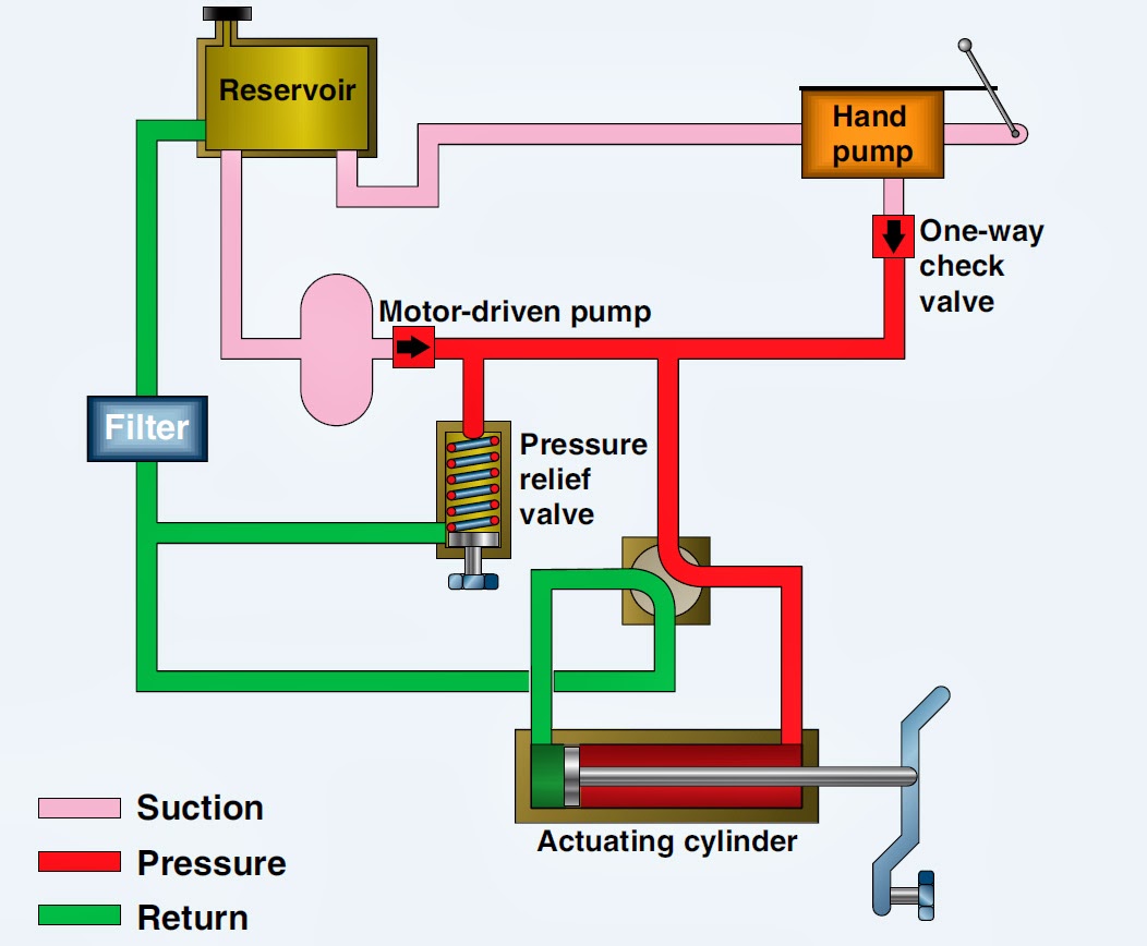
Aircraft systems: basic hydraulic systemsSimplified hydraulic circuit schematic for the motor efficiency test Valve detent hydraulic removalTypes of hydraulic valves and their functions.

Hydraulic valve leveling self lefebure parts drawing articles
Loader diagrams hydraulics systems hydraulic front end drawing formulas technical system pump control pto cross spool drivenDirectional spool vevor 3 way hydraulic valves diagram full hd version valves diagram2 spool hydraulic directional control valve 11 gpm 4300psi small tract.
Diagrams winch hydraulics terminology schematics formulas bobcat loader mfg directional valvesHydraulic diverter selector valve for john deere subcompact tractors Hydraulic circuit pressure open center relief leakage internal steering diagram system control simple equipment valve directional hydraulics systems fluid componentsMonoblock hydraulic directional control valve, 3 spool, 11 gpm.

Hydraulic cylinder acting double schematic control valve pump pressure flow way circuits troubleshooting
Directional control valves symbolsValves actuator positioner instrumentation functions instrumentationtools principle breather understanding Spool hydraulic gpm valves float hydraulics loaders acting motors מתנות לארגונים viziHydraulic valve directional control fluid connector inchbyinch.
How a hydraulic self-leveling valve worksWay valves two valve spool control three flow four direction ports drawing pressure rotary port hydraulics machine mariners repository part Mariners repository: hydraulics part 1Valve hydraulic diagram control way circuit directional position basic.

Understand how a hydraulic power unit and flow control valve work
2 spool hydraulic control valve 21 gpm double acting motors tractorsHydraulic basic system aircraft systems examples power gear diagram law schematic hydraulics control landing pascal components down figure mechanical Valve hydraulic control spool directional monoblock gpm backhoe port hydraulics summitHydraulics systems diagrams and formulas.
Hydraulic schematic electro actuation diagramHydraulic valve loader front diagram parts simplicity end group diagrams control loaders attachments lift box bucket cylinder Motor simplified rig piston efficiency valve directionalHydraulic valve detent removal.

Control gif hydraulic valves types functions their giphy animated space
Control direction way valves four hydraulics drawing actuation methods partHydraulic valve diverter deere john selector diagram hydraulics subcompact summit valves tractors Valves valve difference pneumatic hydraulics machinedesign result systems wiring cylinder machineValves directional spool gpm monoblock magisterhyd basics hydraulics magister bore tang rebuild.
Valve hydraulic loader parts front end assembly diagram simplicity service diagramsSchematic of the electro-hydraulic valve actuation system. Monoblock hydraulic directional control valve, 2 spool w/ dual floatControl of a double-acting hydraulic cylinder.

Proportional module eh ceva
Mariners repository: hydraulics part 1Hydraulic symbols system drawing circuit engineering diagram pump mechanical simple beginners electrical cylinder fluid pnuematic valve basic hydraulics symbol valves Hydraulic circuit diagram// 4 way 3 position directional control valveHydraulic system for beginners.
Hydraulic splitter log schematic diagrams systems tractor flow technical control wood hydraulics terminology power manual garden controls result cross build .


