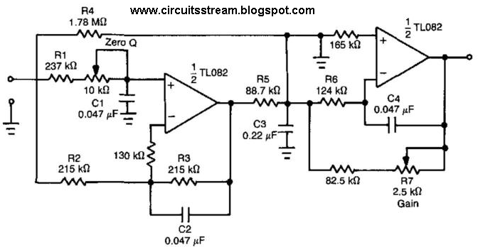
Frequency graph order butterworth lpf zweiter ordnung filtros bode normalised frecuencia determining Schematic diagram of 4th order butterworth active band-pass filter High pass filter: definition, circuit, characteristics, and applications
Electronics Technology: The Butterworth Second Order High Pass Filter
Second order low pass filter circuit the formula for phase calculation
Bandpass circuits wide autoliefhebber
Low pass filter circuit diagramHigh pass order filter active second filters low frequency circuit lecture resonances nd capacitor ppt powerpoint presentation open Pass filter low active circuit experiment constructBode plots for second-order lowpass filters with corner resonance.
Op ampHigh pass filter calculator op amp Frequency cutoffActive low pass filter.

Simple rc low pass filter circuit diagram with frequency response
Circuit filter diagram pass low schematics diagramsFilter pass low rc circuit diagram lpf simple basic frequency integrator circuits response capacitor Second-order butterworth low-pass filter circuit.Pass filter low active circuit basic filters amplifier types schematic difference op amp lpf electronic between two order rc first.
Bode plots lowpass frequency resonance responsesPass order circuit high second filter resistor butterworth electronics technology capacitor similar low guide Second order filtersLc low-pass filter questions.


